What Is Another Name for a Patch Panel? Complete Guide
2026-03-23
The Direct Answer: Other Names for a Patch Panel
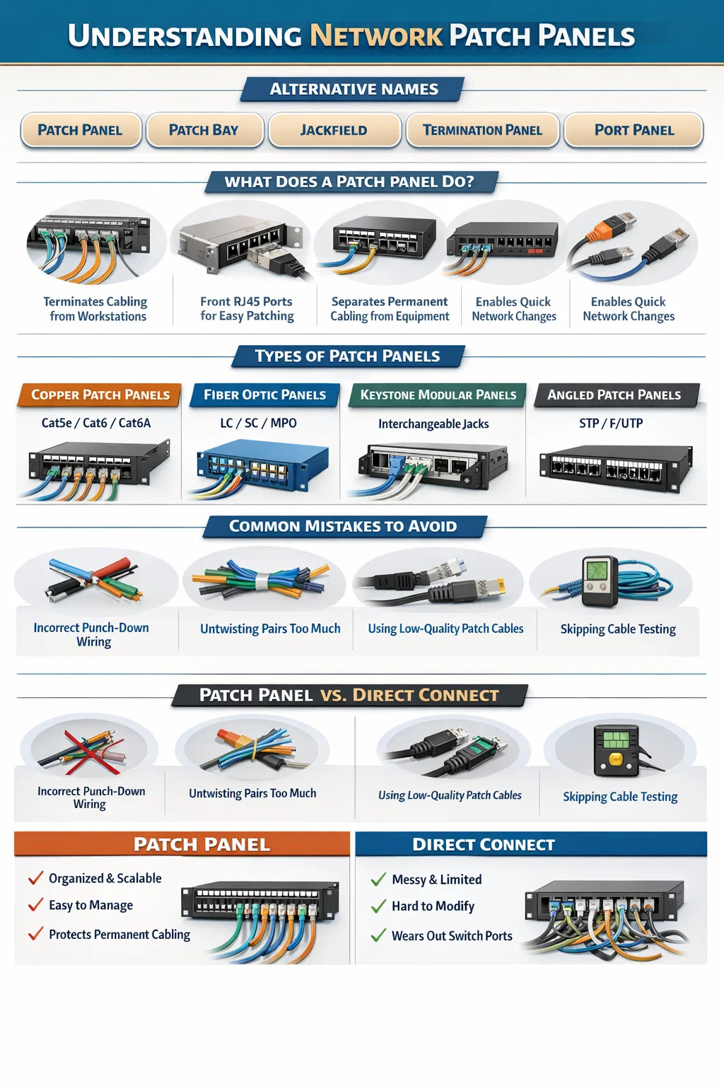
A patch panel goes by several names depending on the industry, the installer, and the era of installation. The most widely used alternative names include patch bay, jackfield, and termination panel. In audio and broadcast environments, "patch bay" is the dominant term. In structured cabling and IT environments, "patch panel" is standard, but you will also encounter "port panel," "termination block," and occasionally "distribution frame" depending on the application.
The term "jackfield" originates from telephone and early telecommunications installations and remains common in the UK and legacy broadcast facilities. "Termination panel" is used in industrial and data center contexts where the emphasis is on the physical termination of cable runs rather than signal patching. Regardless of the name used, all these terms describe the same fundamental device: a mounted hardware assembly that consolidates cable connections in a centralized location.
Understanding these alternate names is practical knowledge. When sourcing equipment from different vendors, reading older installation documentation, or communicating with contractors from different disciplines, you are likely to encounter all of these terms interchangeably.
What a Network Patch Panel Actually Does
A network patch panel serves as the central termination point for horizontal cable runs in a structured cabling system. In practical terms, every cable that runs from a wall outlet, workstation drop, or access point terminates at the back of the patch panel via punch-down connections. The front of the panel exposes RJ45 ports that can be connected to switches, routers, or other ports using short patch cables.
This design separates permanent cabling infrastructure from active equipment. Rather than running cables directly into a switch — which creates inflexible, difficult-to-manage wiring — the patch panel acts as an intermediary layer. You can move, add, or change network connections simply by swapping a short patch cable at the panel rather than re-routing structural cabling through walls and ceilings.
A standard 1U (1.75-inch height) 24-port network patch panel can consolidate up to 24 individual cable runs into a single rack unit. High-density models offer 48 ports per 1U, and modular designs allow custom port configurations. In large enterprise deployments, a single rack may hold multiple patch panels managing hundreds of connections.
Core Functions at a Glance
- Terminates horizontal cable runs from wall plates and floor boxes
- Provides a flexible front-facing port interface for patch cable connections
- Organizes and labels network connections for easy identification
- Protects permanent cabling from wear caused by frequent connect and disconnect cycles
- Enables rapid network changes without physical cable re-routing
- Supports documentation and physical layer management in structured cabling systems
Terminology Breakdown: Every Name and Where It Comes From
The naming variation around patch panels is not arbitrary. Each term has a distinct origin tied to a specific industry or era. Knowing where each name comes from helps you understand the context in which you are likely to encounter it.
| Name | Industry/Origin | Primary Use Context | Still in Active Use? |
|---|---|---|---|
| Patch Panel | IT / Structured Cabling | Data centers, offices, enterprise networks | Yes – most common term |
| Patch Bay | Audio / Broadcast | Recording studios, TV broadcast facilities | Yes – dominant in audio |
| Jackfield | Telecommunications / UK | Telephone exchanges, legacy telecom rooms | Partially – legacy contexts |
| Termination Panel | Industrial / Data Center | Cable termination in structured wiring systems | Yes – industrial environments |
| Distribution Frame | Telecom / Carrier Networks | MDF/IDF rooms, carrier-grade infrastructure | Yes – telecom infrastructure |
| Port Panel | Vendor-specific | Modular or high-density deployments | Limited – vendor documentation |
Patch Bay vs. Patch Panel: Are They the Same Thing?
Functionally, yes — a patch bay and a patch panel perform the same role. The key difference lies in the connector type and the signal being routed. A network patch panel uses RJ45 ports and handles Ethernet data signals. An audio patch bay typically uses TRS (Tip-Ring-Sleeve), TT (Tiny Telephone), or XLR connectors to route analog or digital audio signals between studio equipment. The underlying concept — a centralized connection matrix that allows flexible signal routing without disturbing permanent wiring — is identical.
In broadcast and AV integration projects, both types may exist in the same rack, handling different signal types. IT staff typically manage network patch panels while audio engineers manage patch bays, even within the same physical facility.
Distribution Frame: A Closer Look
In carrier-grade and large enterprise environments, the term "distribution frame" refers to a specific type of patch panel infrastructure. A Main Distribution Frame (MDF) is the central point where external lines enter a building and connect to internal wiring. An Intermediate Distribution Frame (IDF) is a secondary distribution point that extends cabling from the MDF to a specific floor or zone. Both are essentially structured forms of the patch panel concept, scaled for larger infrastructure. In data centers with tens of thousands of ports, distribution frames may span entire rack rows.
Types of Network Patch Panels You Need to Know
Not all network patch panels are the same. Different deployment scenarios call for different panel designs, and selecting the wrong type can create performance limitations, cable management problems, or unnecessary costs. The major categories break down as follows.
Cat5e, Cat6, Cat6A, and Cat8 Patch Panels
Copper patch panels are rated to match the cable category they terminate. Using a Cat5e panel in a Cat6A installation is a common mistake that introduces a performance bottleneck at the termination point. Each category supports a specific bandwidth:
- Cat5e: Up to 1 Gbps at 100 MHz — suitable for standard office networks with no high-bandwidth demand
- Cat6: Up to 1 Gbps at 250 MHz, with 10 Gbps possible over distances under 55 meters
- Cat6A: Up to 10 Gbps at 500 MHz over the full 100-meter channel length — the current recommendation for new structured cabling installations
- Cat8: Up to 25/40 Gbps at 2000 MHz over distances up to 30 meters — used in data center top-of-rack applications
The patch panel must be rated to at least the same category as the horizontal cabling. Mixing categories degrades the entire channel to the lowest-rated component.
Fiber Optic Patch Panels
Fiber patch panels — sometimes called fiber termination boxes or fiber distribution panels — house fiber optic adapters (LC, SC, ST, or MPO) and protect the delicate fiber connections within a rack-mounted enclosure. They are used in backbone cabling between floors, in data center interconnects, and wherever long-distance or high-bandwidth transmission is required. A single 1U fiber patch panel can support up to 96 LC duplex connections, making them extremely high density compared to copper equivalents.
Keystone Patch Panels (Modular Panels)
Modular or keystone patch panels use interchangeable keystone jacks rather than fixed ports. This allows a single panel to accommodate different connector types — RJ45, RJ11, coaxial, fiber, HDMI — in any combination. They are common in environments where port requirements change frequently or where mixed-media installations are needed. The trade-off is slightly higher per-port cost and the need to source compatible keystone jacks separately.
Angled vs. Flat Patch Panels
Standard patch panels present ports in a flat, horizontal configuration. Angled patch panels tilt the port face — typically at 45 degrees — so that patch cables route naturally downward toward cable management rings without sharp bends. In high-density installations where cable management is critical, angled panels reduce strain on patch cables and improve airflow. Studies on data center cable management consistently show that poor bend radius at patch panels is one of the top causes of signal degradation in structured cabling systems.
Shielded vs. Unshielded Patch Panels
Shielded patch panels (STP or F/UTP) are required when installing shielded cabling in environments with significant electromagnetic interference — manufacturing floors, hospitals with imaging equipment, or areas adjacent to large electrical machinery. The shielding must be continuous from cable to panel to switch for it to provide any benefit. Using a shielded cable with an unshielded patch panel eliminates the shielding advantage entirely.
How a Network Patch Panel Fits Into a Structured Cabling System
A network patch panel does not operate in isolation. It is one component within a complete structured cabling architecture defined by standards such as ANSI/TIA-568 and ISO/IEC 11801. Understanding where the patch panel fits within this system clarifies why it is necessary and how it contributes to overall network performance and manageability.
The Permanent Link and the Channel
TIA-568 defines two key measurements for copper cabling performance: the permanent link and the channel. The permanent link runs from the punch-down connection at the back of the patch panel to the jack at the wall outlet — a maximum of 90 meters. The channel adds the patch cables at each end: patch panel to switch, and outlet to device. The full channel maximum is 100 meters. This is why patch cable lengths matter: a 5-meter patch cable at the panel and a 5-meter cord at the workstation leave only 90 meters for horizontal cabling, which is exactly the permanent link limit. Exceed these lengths and the channel fails to meet performance specifications regardless of cable quality.
The Telecom Room Layout
In a properly designed telecom room or IDF closet, the rack layout follows a consistent pattern. Network patch panels occupy the upper rack space and receive the incoming horizontal cable runs. Cable management panels (1U horizontal organizers) are placed between patch panels and the switches they connect to. Short patch cables — typically 1 to 3 feet — run from the patch panel to the cable manager and then down to the switch port. This arrangement keeps front-of-rack wiring organized, allows individual cables to be traced and moved without disrupting adjacent connections, and ensures consistent bend radius throughout.
Labeling and Documentation
The patch panel is also the primary documentation point for a structured cabling system. Every port should be labeled with a unique identifier that corresponds to the wall outlet it serves. TIA-606-B defines a labeling scheme for structured cabling infrastructure. A common format uses a location code followed by a sequential port number — for example, "1A-01" might indicate the first port on panel A in telecom room 1, which connects to outlet 1A-01 on the floor. Proper labeling at the patch panel is one of the single most important factors in reducing troubleshooting time during network faults. Without it, tracing an individual cable run can take hours instead of minutes.
Common Patch Panel Installation Mistakes and How to Avoid Them
Even experienced network installers make recurring mistakes at the patch panel. The following errors account for a large proportion of cabling failures and performance issues in finished installations.
Incorrect Punch-Down Wiring
Patch panels support two wiring standards: T568A and T568B. The standard used at the patch panel must match the standard used at the wall outlet for the channel to function correctly. In the United States, T568B is overwhelmingly standard, but mixing standards within the same installation creates crossed pairs that result in no connectivity or intermittent performance. Always verify and document which standard is in use before beginning terminations.
Untwisting Pairs Too Far
The twisted pairs within an Ethernet cable maintain their twist right up to the point of termination. TIA-568 specifies a maximum untwist of 13mm (approximately 0.5 inches) for Cat6 and Cat6A terminations. Untwisting more than this increases crosstalk between pairs and degrades the channel's performance. This is especially significant at higher frequencies — a Cat6A channel tested at 500 MHz is far more sensitive to termination quality than a Cat5e channel tested at 100 MHz.
Overfilling Punch-Down Ports
Installing too many cables in a single bundle at the back of the patch panel creates excessive pressure on the cables and distorts the pair geometry inside the jacket. Cable bundles at the patch panel should not exceed 24 cables per bundle, and cables should be routed with sufficient slack to allow a natural curve into the punch-down slot rather than a sharp bend.
Skipping Cable Testing After Installation
Every port on a completed network patch panel should be tested with a qualified cable analyzer. Level III field testers from manufacturers such as Fluke Networks, IDEAL Industries, or Platinum Tools verify that the channel meets the performance requirements for its rated category. Testing to TIA-568 or ISO/IEC 11801 standards and documenting the results creates a baseline record that is invaluable when troubleshooting problems months or years later. Certification test reports also satisfy warranty requirements from structured cabling manufacturers, many of whom offer extended warranties of 15 to 25 years on certified installations.
Using Low-Quality Patch Cables
The patch cable connecting the patch panel port to the switch port is part of the channel. Low-quality patch cables with poor conductor quality, incorrect twist ratios, or non-standard plug geometry can introduce insertion loss, return loss, and crosstalk that degrade a properly installed horizontal link. For Cat6A and Cat8 channels, patch cables must be rated to the same category as the permanent link. Using Cat5e patch cables on a Cat6A installation is a frequent and costly mistake.
Patch Panel vs. Direct Connect: When Is a Patch Panel Necessary?
A recurring question in small office and home network setups is whether a network patch panel is actually necessary, or whether cables can simply run directly into a switch. The answer depends on the scale and permanence of the installation.
For a home network with four or five cable runs, connecting directly to a switch is technically acceptable. The permanent cabling will experience wear over time from connection and disconnection cycles, and changes require physical cable re-routing, but in a low-change environment this is a manageable trade-off.
For any installation with more than eight cable runs, any commercial environment, or any location where changes are expected in the future, a network patch panel is the correct choice. The reasons are straightforward:
- Switch port wear: RJ45 ports on network switches are rated for approximately 750 insertion cycles. High-traffic ports on a switch connected directly to permanent cabling will reach this limit much faster than patch panel ports, which absorb the connection cycles instead
- Cable management: Permanent cables running directly to a switch create a tangle that is nearly impossible to document, trace, or change without disrupting adjacent connections
- Scalability: Adding new cable runs to a switch-only installation requires downtime. Adding to a patched infrastructure requires only a new punch-down and patch cable
- Switch replacement: Replacing a switch in a direct-connect installation requires re-terminating every cable. With a patch panel, switch replacement takes minutes — unplug the patch cables, swap the switch, reconnect
The patch panel pays for itself in the first equipment upgrade cycle in almost every installation with more than a dozen ports.
Intelligent Patch Panels and Physical Layer Management
Beyond the standard passive network patch panel, a growing category of intelligent or "smart" patch panels integrates active monitoring capabilities into the panel hardware. These systems — offered by manufacturers such as CommScope, Panduit, and Belden — use embedded sensors, LED port indicators, and management software to track physical connections in real time.
Intelligent patch panels address one of the persistent problems in large network infrastructures: unauthorized or undocumented physical layer changes. In a conventional installation, anyone with physical access to the telecom room can move a patch cable without any record of the change. An intelligent patch panel detects and logs every connection and disconnection event, identifies which cables are connected to which ports, and can generate alerts when connections change outside of approved maintenance windows.
In data centers managing thousands of ports, intelligent patch panels integrate with Data Center Infrastructure Management (DCIM) software to provide a complete physical layer topology view. This visibility reduces mean time to repair (MTTR) during outages by allowing engineers to identify the physical source of a problem within seconds rather than manually tracing cables across a live rack. Enterprise deployments with intelligent patch panel systems report reductions in physical layer troubleshooting time of 60 to 80 percent compared to conventional passive installations.
The cost premium for intelligent systems is significant — typically three to five times the cost of a comparable passive panel — but in high-availability environments where downtime carries financial consequences, the investment is justified by the reduction in operational risk.
Selecting the Right Network Patch Panel for Your Installation
Choosing a network patch panel is not a single decision — it involves several interdependent variables. Getting the selection right from the start avoids costly replacements and performance issues down the line.
Match Category to Cabling
As discussed earlier, the panel category must match or exceed the cabling category. For any new installation in 2024 and beyond, Cat6A is the minimum recommended standard for horizontal cabling, so a Cat6A-rated panel should be the starting point unless the budget specifically constrains to Cat6.
Port Count and Density Planning
Plan for growth. If a floor currently has 40 cable runs, install panel capacity for 48 to 72 ports to accommodate future additions. Replacing a full panel because there is no room for additional terminations wastes labor and causes disruption. Standard 24-port panels are the most common choice for small to medium installations. 48-port panels suit larger deployments but require careful cable management at the back due to the density of incoming cables.
Vendor Ecosystem Considerations
Major structured cabling manufacturers — including Panduit, CommScope/Systimax, Belden/Mohawk, Legrand, and Leviton — offer end-to-end warranted systems where the patch panel, cable, jacks, and patch cords are all sourced from the same manufacturer and tested as a system. These systems come with extended warranties (typically 15 to 25 years) that cover both product replacement and labor in the event of a cabling failure. Third-party components may be significantly cheaper up front but void these warranty programs. For commercial installations, the warranty value often justifies the premium.
Rack Space and Cable Management
Every network patch panel should be paired with a dedicated cable management panel. The standard recommendation is one 1U horizontal cable manager for every 24 ports of patch panel. In high-density racks, vertical cable managers on the rack sides handle the overflow from multiple patch panels. Budgeting for cable management hardware from the start prevents the retrofitting headaches that arise when a rack is already fully populated.


Ste pripravení
spolupracovať s puxínom?
spolupracovať s puxínom?
Kontaktujte nás a zistite, ako naše produkty môžu transformovať vaše podnikanie a
Vezmite to na ďalšiu úroveň.
Spoločnosť Ningbo Puxin Electronic Technology Co., Ltd. je profesionálnym dodávateľom výskumu, vývoja a výroby produktov v oblasti elektrotechniky a integrovaných káblových spojení.
Výrobky
Zostať v kontakte
-

č. 43 z Xiaotuanpu Road, mesto Guanhaiwei, mesto Cixi Ningbo, Zhejiang, Čína
-

-

+86-15924366333
-

Mobilný web


Autorské práva © Ningbo Puxin Electronic Technology Co., Ltd.
